The diagram below shows SUB-20 power distribution and voltage levels.
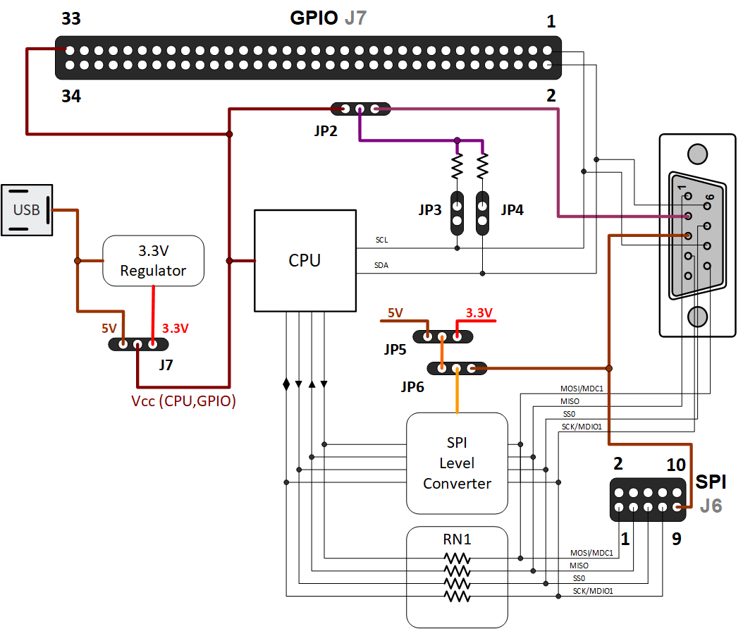
CPU and GPIO Voltage
CPU and GPIO voltage is defined by J7. It can be 5V from the USB or 3.3V from the internal regulator. In customized SUB-20 models 3.3V regulator can be exchanged with 2.7V .. 5V regulator.
It is possible to source up to 70mA from GPIO33 to power external target.
I2C Voltage
I2C voltage is defined by I2C pull-ups voltage. If pull-ups are enabled with JP3, JP4 I2C voltage is controlled by JP2. It can be internal 5V or 3.3V or external taken from DB9.2. External I2C voltage is not available in SUB-20-R25 (Serial2) model.
SPI/MDIO1 Voltage
SPI Level Converter and RN1 resistors network are mutually exclusive. SPI Level Converter is available in SUB-20-Lxxx models.
•If SPI Level Converter installed SPI/MDIO1 voltage is defined by JP5 and JP6. It can be 5V or 3.3V if JP6 is configured for internal voltage or externally referenced if JP6 is configured for external voltage. External voltage can be taken from SPI.9 or DB9.3 (in non Serial2 model).External voltage reference can be in range 1.6V .. 5V for SUB-20-Lxxx models or 1.2V .. 3.3V for SUB-20-Lxxx-1.2 models. Models with SPI Level Converter can not be used in SPI Slave mode.
•If SPI Level converter is not installed RN1 is used to rout SPI/MDIO1 signals to SPI header and DB9 connector. SPI/MDIO1 voltage in this case is defined by CPU Voltage.